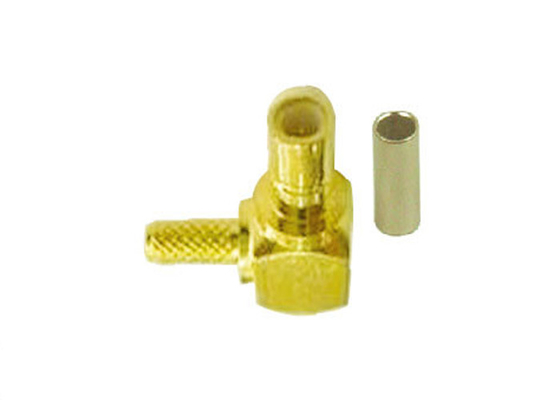
Product Details:
|
Impedance: | 50 Ω | Frequency Range: | 0-4 GHz With Low Reflection; Usable To 10.0 GHz |
---|---|---|---|
Voltage Rating For RG-188/U Cable: | 335 Volts At Sea Level And 85 Volts At 70,000 Feet | Dielectric Withstanding Voltage: | RG-196: 750 VRMS; RG-188: 1,000 VRMS |
VSWR: | Straight Connector, RG-196/U: 1.30 + .04 F (GHz) Right Angle Connector, RG-196/U: 1.45 + .06 F (GHz) Straight Connector, RG-188/U: 1.25 + .04 F (GHz) Right Angle Connector, RG-188/U: 1.35 + .04 F (GHz) | Contact Resistance: | Center Contact: 6.0 MΩ Initial, 8.0 After Environmental; Outer Contact: 1.0 MΩ Initial, 1.5 After Environmental Braid To Body: 1.0 MΩ Initial, After Environmental N/A |
Insulation Resistance: | 1,000 MΩ Minimum | Insertion Loss: | Straight Connector: 0.30 DB @ 1.5 GHz Right Angle Connector: 0.60 DB @ 1.5 GHz |
RF Leakage: | -55 DB Minimum @ 2-3 GHz | ||
High Light: | RF Coaxial SMA Male Crimp Connector,RG316 Cable SMA Male Crimp Connector,Full Brass Straight SMA RF Connectors |
High Quality Full Brass RF Coaxial Straight SMA Male Crimp Connector For RG316 RG174 Cable
Electrical |
||
Impedance |
50 Ω |
|
Frequency Range |
0-4 GHz with low reflection; usable to 10.0 GHz |
|
Voltage Rating for RG-188/U Cable |
335 volts at sea level and 85 volts at 70,000 feet |
|
Dielectric Withstanding Voltage |
RG-196: 750 VRMS; RG-188: 1,000 VRMS |
|
VSWR |
Straight connector, RG-196/U: 1.30 + .04 f (GHz) |
|
Contact Resistance |
Center contact: 6.0 mΩ initial, 8.0 after environmental; |
|
Insulation Resistance |
1,000 MΩ minimum |
|
Insertion Loss |
Straight connector: 0.30 dB @ 1.5 GHz |
|
RF Leakage |
-55 dB minimum @ 2-3 GHz |
|
Mechanical |
||
Mating |
Snap-on coupling per MIL-STD-348 |
|
Braid/Jacket Cable Affixment |
Hex crimp |
|
Center Conductor Cable Affixment |
Solder |
|
Contact Captivation |
All types unless noted otherwise |
|
Cable Retention |
Equal to breaking strength of cable employed |
|
Engagement Forces |
Engagement: 14 lbs maximum |
|
Connector Durability |
500 mating cycles minimum |
|
Material |
||
Center Contact |
Female: beryllium copper, gold-plated |
|
Outer Contact Plating |
Nickel or gold plating as indicated |
|
Body |
Brass per QQB-626, or zinc per ASTM B86-71 |
|
Body Plating |
Nickel or gold plating as indicated |
|
Insulator |
TFE |
|
Crimp Ferrule |
Annealed copper alloy |
|
Environmental |
||
Temperature Range |
- 65°C to +165°C |
|
Thermal Shock |
MIL-STD-202 method 107, test condition B (except high temperatures @ 200°C |
|
Shock |
MIL-STD-202 method 202, method 13, snap-on, test condition B; 75 G's @ 6 milliseconds ½ sine |
|
Vibration |
MIL-STD-202 method 204, snap-on, test condition B; (15 G's) |
|
Corrosion |
MIL-STD-202 method 101, test condition B. 5% salt solution |
To better ensure the safety of your goods, professional, environmentally friendly, convenient and efficient packaging services will be provided.
FAQ :
Q: What's your company MOQ?
A: In generally, we will ask at least 100~1000pcs, this we can negotiate.
Q: What's your delivery time?
A: This please check our stock in first, products can be sendtout once receive your payment. Usually, 7-14 days for mass production.
Q: Can your company accept customize?
A: Welcome OEM & ODM.
Q: How do you solve after sale service?
A: One year guarantee. Replacement of defective ones after negotiation.
Q: Can you send a sample for us to develop?
A: Yes, we can. Sample can be sent out once you ask for it, but will ask a sample fee.
Contact Person: Jennifer Song
Tel: 86 13599545657